A question about paneling
Nobody asks you to check the frame. They ask about the paneling, and the frame is what is behind it.
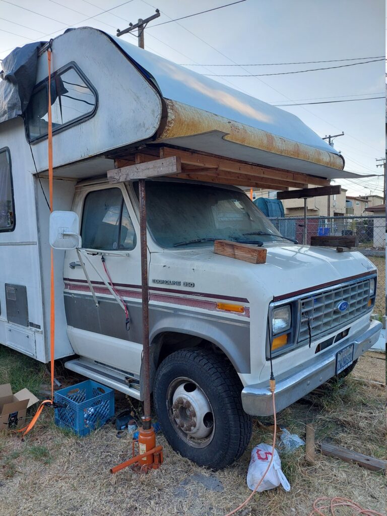
The stuck thing
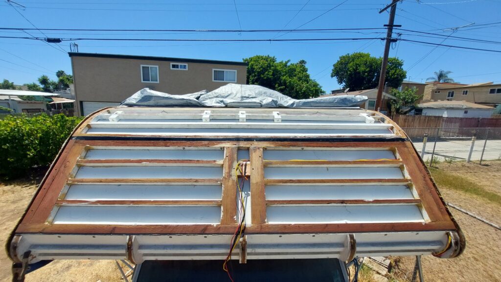
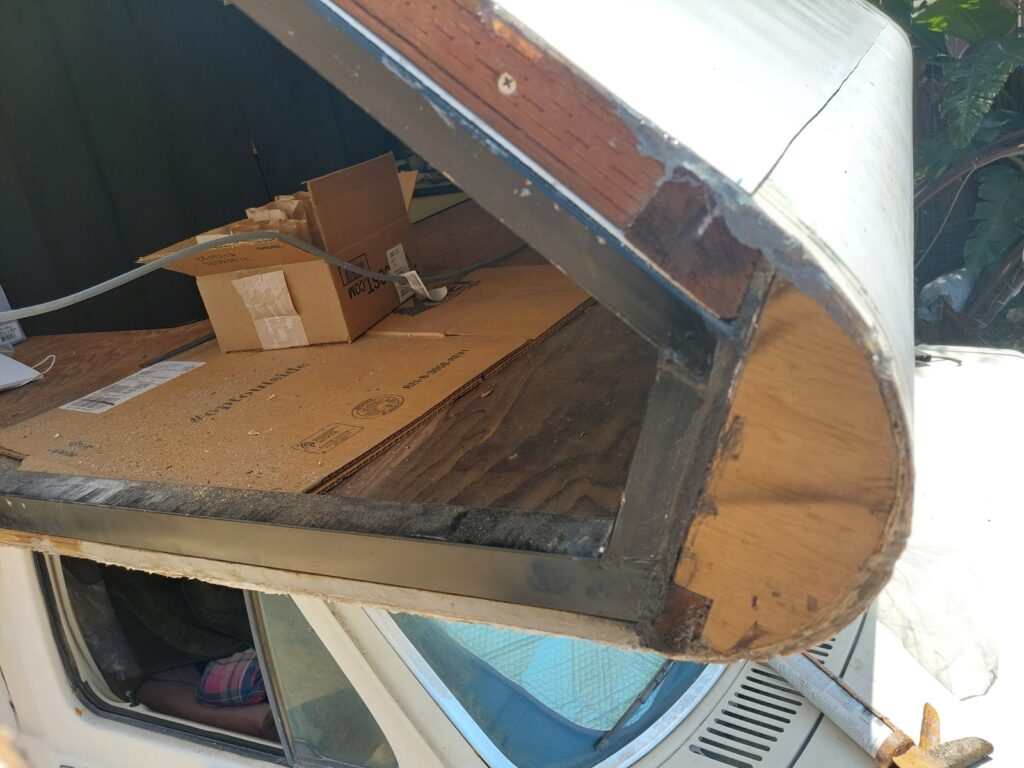
A friend asked what it would take to replace the wood paneling inside his motorhome’s cabover — the bunk that overhangs the cab. Delaminating panel is a cosmetic complaint. But, unbeknownst to him, water had been coming in at the exterior joints for years, and behind the panel the news got worse at every layer: the wood subframe disintegrated, the ¾-inch plywood floor coming apart in the hand, and the steel tube subframe corroded through, with no structural integrity left in it at all. What was still holding the cabover together was the outer fiberglass sheath and the molding around it.
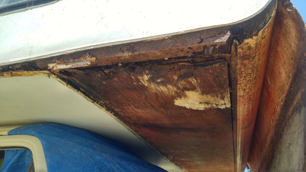
That is a box, cantilevered over the driver’s head, at freeway speed. At highway windspeeds it could have opened up like a sardine can.
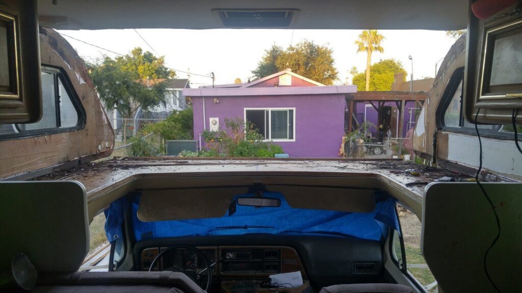
The diagnosis
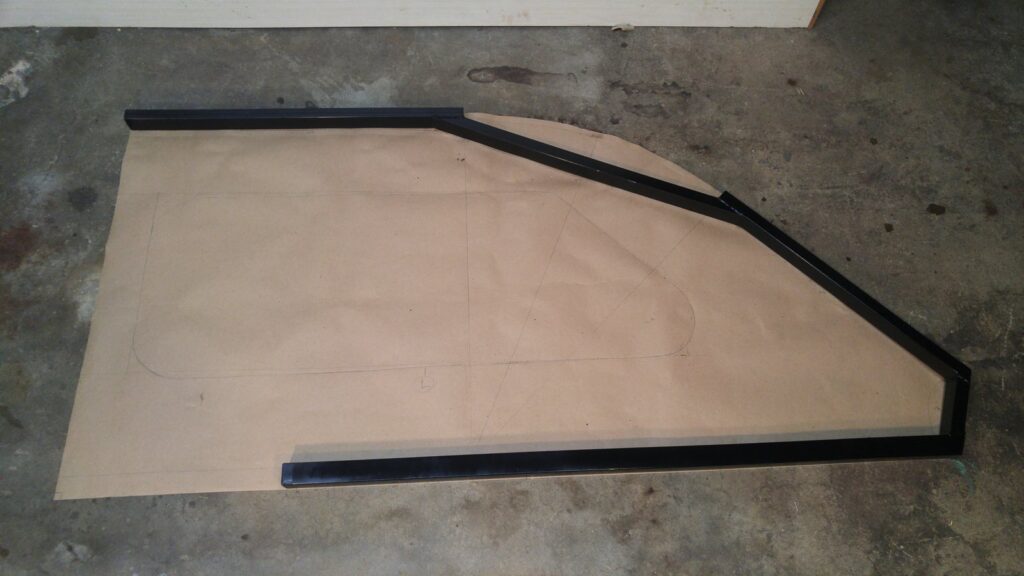
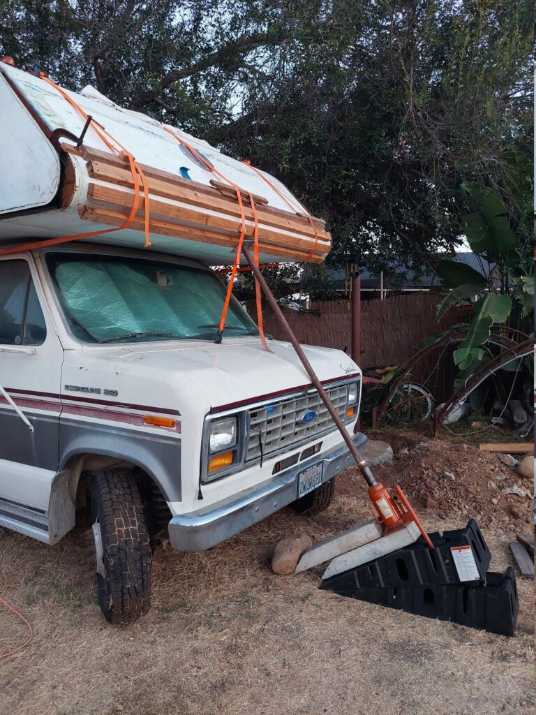
Nothing could be judged until it was open, so it came open. Paneling out, sheath off, the front window removed entirely, and every member cut back until the material was sound. Then what was left got measured and redrawn, because a coach this age has no drawings and the body has moved since it was built. Side frame and panel, top radius, front window paneling: dimension by dimension on graph paper, then a materials list, then steel.
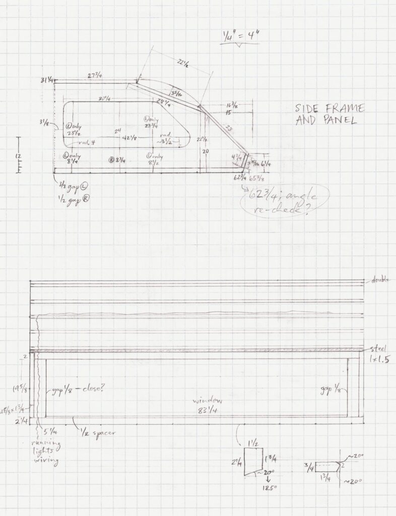
The knowledge for the frame came from a truck-body line in 1992. Morgan Corporation builds box bodies and mounts them on chassis, and I worked every station on that line — the subframe jig, flooring sidewalls, radius and corner caps, roofing, mount bay. A motorhome cabover is the same problem stated differently: a box that has to hold its shape while the frame under it flexes and the wind tries to lift its leading edge. Twenty-nine years between the two jobs, and none of it had gone anywhere.
Made it go
A new steel subframe, welded and set. New floor, new bed platform, new paneling cut from full-size patterns, the front window removed at the owner’s request (for a darker bedroom), the sheath re-bonded and the whole front sealed. Months of work. One person. No shop.
Some side repairs: the fuel tank dropped and the pump replaced, and the ignition repaired at the steering column.
It does look like a white horse
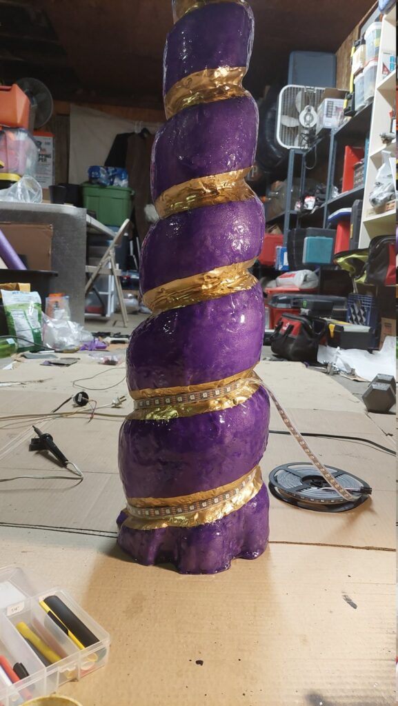
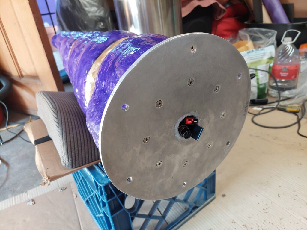
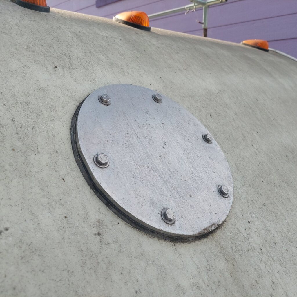
…I think it needs a unicorn horn. That was my offhand observation to the client about the finished coach, and it turned into a second commission. Three feet of purple fiberglass over a wood and metal frame, wrapped in a gold spiral, with chasing RGB LEDs, a multi-pattern strobe, and a music-reactive mode. The constraints did some of the designing: no taller than the roof air conditioner behind it; twelve volts, because of the cable run; and removable — bolted down, weather-sealed, with a cap for the mount, because the roof has to stay watertight when not sporting the horn. But the form came from finding a picture of a stuffed, spiraled horn on the internet.
The roof framing was already built by then. Hanging three feet of fiberglass off it at freeway speed meant re-engineering that framing and building it a second time.
The frame had been a long run of bad news — every layer I opened was worse than the last, and he took the reports the way anyone would. This was the first part of the job he was glad about. I said it once; after that it was never going to go undone.
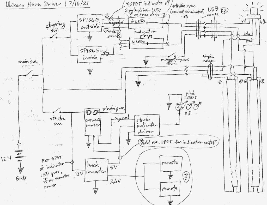
The frame was the part I already knew how to do. This was the part I didn’t. I worked out the geometry from scratch, built sleds for the table saw before anything could be cut, had never laid fiberglass in my life, and learned enough electronics to integrate a controller from components rather than buy a module and hope.
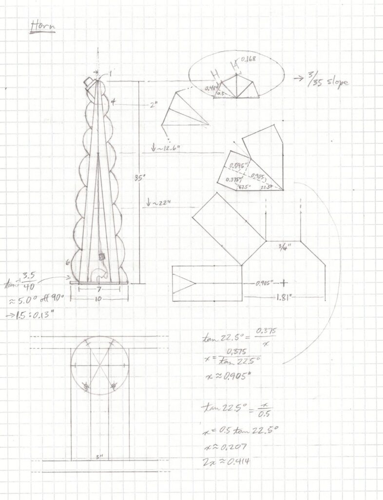
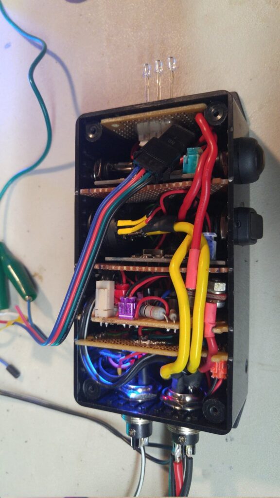
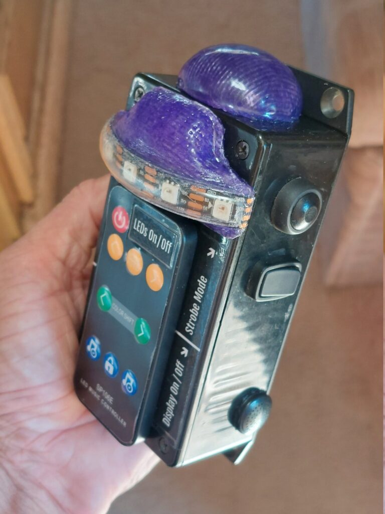
None of it could be bought, so all of it got made: dimensioned drawings, jigs built to produce the parts, a laminated spine cut on the table saw, a foam form, glass laid over the form, a machined aluminum base, and a control box prototyped on a breadboard and then built to a hand-drawn driver schematic — buck converter, strobe driver, current sensor, chase and strobe switches, Tetris’d and sealed behind an engraved face. It was on the roof in time for the event it was built for.
It was also, as I said at the time, a spectacular way to shoot yourself in the foot during an RV rebuild.
structural welding · fabrication · measurement & drafting · fiberglass · 12V systems · circuit design & prototyping · weather sealing
← All work · Have a stuck thing? Tell me about it →